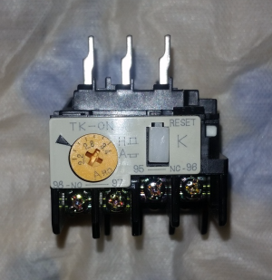
Hand reset position in.
Thermal overload relay setting calculation.
Min thermal over load relay setting 70 x7 5 amp.
Max thermal over load relay setting 120 xfull load current phase max thermal over load relay setting 120 x7 9 amp.
Hence overload must be chosen closer to the range of 8 6 14 7.
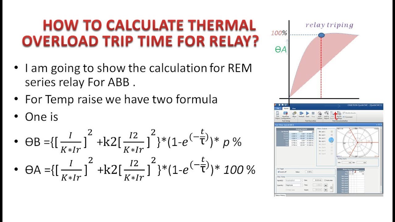
Thermal overload relay is simple over current protection it does not protect from single phasing or phase failure short circuit and earth fault the operating principle of the relay is when current flow through a conductor increases then i 2 x r loss also increases heat loss or ohmic loss.
Calculation of idmt over current relay settings 50 51 50n 51n calculation model for thermal relay siemens 7sj64.
However if motors are designed with a service factor which is then shown on the nameplate eg.
According to nec the general requirement for overload sizing be set around 115 or 125 from full load ampere we should setting the overload relay within this parameter to avoid electric motor from serious damage.
Thermal overload relay setting 70 x12 28 8 6a max.
I hope you will find this article informative and helpful.
What load current value should the overload relay be set at.
Thermal overload relay setting 120 x12 28 14 7a.
For a star delta starter we have the possibility to place the overload protection in two positions in the line or in the windings.
Over current protection inverse time o c protection calc 51 n directional oc primary secondary current calculation.
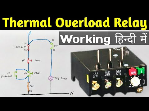
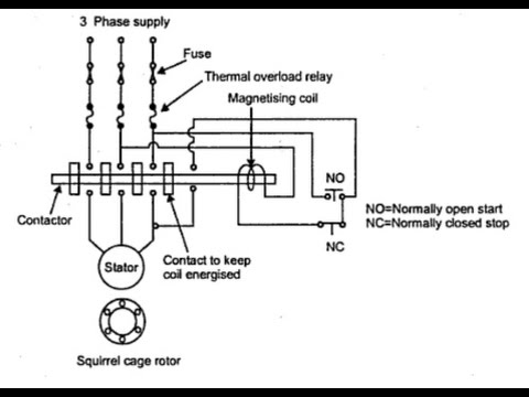
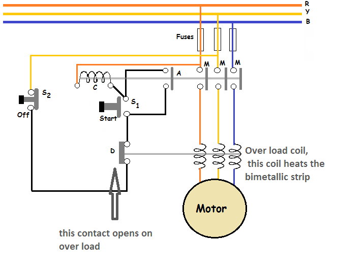
Hi friends in this article i am talking about thermal overload relay working principle and its function in a dol starter.
Motor protection relay selection curves.
2 check your full load ampere using clamp on meter for actual value and compare with your setting.
If o l relay.
If the motor is connected in star 440 v 60 hz the overload relay then has to be set to 3 1 a.
Thermal over load relay vs ct operated thermal overload relay.
Should the overload relay be set to the hand reset or auto reset position.
Selection of thermal overload.
If your compressor always trip 1 use your actual fla value and make calculation and set a new setting for your overload relay.
Thermal overload relay setting 70 x full load current phase min.
Thermal over load relay line.
1 15 the set current for the overload relay can be raised by 15 compared to full load current or to the service factor amps sfa which is normally indicated on the nameplate.
1 check your overload relay condition perform test trip to ensure it is function properly if not change it.
A thermal overload relay works on the heat produced by the excessive overload current the heat produced by the overload current is utilized to trip the motor circuit.
Thermal element 49 provides starting and overload protection based on motor nameplate rating separate model for rotor and stator takes into account negative sequence heating effect short circuit protection guideline instantaneous phase set at 2 times ilr set at 1 2 times ilr 10 15 cycle delay ground.